Torque at Constant Speeds
Introduction
Most wind turbine extract power from the wind in mechanical form and transmit it to the load by rotating shafts. These shafts must be properly designed to transmit this power. When power is being transmitted through a shaft, a torque T will be present. This torque is given by:
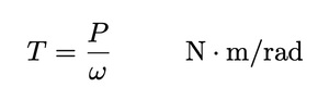
Where P is mechanical power in watts and ω is angular velocity in rad/s. The torque in the low speed shaft of Figure 1 is Tm=Pm/ωm while the torque in the high speed shaft is Tt=Pt/ωt. The units may be expressed as either N∙m/rad or N∙m, depend on one’s preference. Sometime, we shall express torque in rotating shafts in N∙m/rad and torque on a stationary structure such as a tower in N∙m.
The application of torque to a shaft causes internal force or pressures on the shaft material. Such a pressure is called the stress fs with units Pa or N/m2. Since this pressure is trying to shear the shaft, as opposed to compress or stretch, it is referred to as the shearing stress. The shearing stress varies with the distance from the shaft axis, having the largest value at the surface of the shaft. It is shown in textbooks on Mechanics of Materials that the sheering stress in a solid shaft is given by:
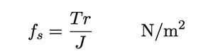
Where r is the distance from the axis of the shaft to where the stress is to be determined, and J is the polar moment of inertia of the shaft. It is given by:
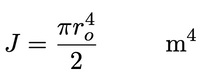
Where ro is the shaft radius.
It should be mentioned that there are two distinct but closely related quantities which are both called the moment of inertia. One is the area moment of inertia, with units m4, and the other is the mass moment of inertia, with units kg∙m2. The area moment of inertia is used in studying the mechanics of materials, normally in a static or stationary mode, while the mass moment of inertia is used in determining the dynamics of rotating structures. These topics are usually covered in separate textbooks, so the prefixes area or mass are usually omitted, with the reader expected to know which one is meant by the context. We shall sometimes omit the prefixes also, but we shall use the symbol J for the polar area moment of inertia and the symbol I for the polar mass moment of inertia. We have no need for the rectangular moment of inertia in this text, so we can drop the word polar from the terminology.
The mass moment of inertia is found from the area moment of inertia by multiplying by the area density ρa in kg/m2. The area density is measured across the area perpendicular to the axis of rotation.
One way of designing shafts to carry a given torque is to select a maximum shearing stress which will be allowed for a given shaft material. This stress occurs at r=r, so Eq. 36 and 37 can be solved for the shaft radius. The shaft diameter which will have this maximum stress is:
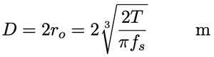
The maximum stress in Eq. 5 is usually selected with a significant safety factor. Recommended maximum stresses for various shaft materials can be found in machine design books.
Example 1
A solid steel shaft has a radius of 0.1 m and a length of 0.8 m. Find the area moment of inertia J and the mass moment of inertia I if the volume density of steel is 7800 kg/m3.
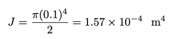
The area moment of inertia is given by Eq. 3 as:
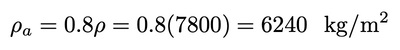
The area density of the shaft would simply be the length times the volume density:
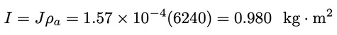
The mass moment of inertia is then:
Example 2
You are designing a wind turbine with an electrical generator rated at 200 kW output. The low speed shaft rotates at 40 r/min and the high speed shaft rotates at 1800 r/min. Solid steel shafts are available with recommended maximum stresses of 55 MPa. The gearbox efficiency at rated conditions is 0.94 and the generator efficiency is 0.93. Determine the necessary shaft diameters.
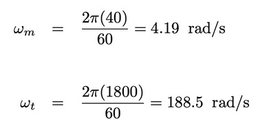
The angular velocities for the low and high speed shafts are:
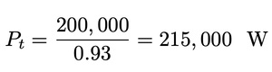
The power in the high speed shaft is:
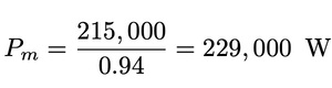
The power in the low speed shaft is:
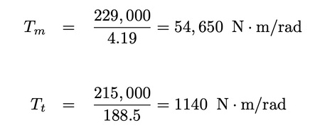
The torques are then:
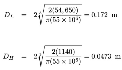
The shaft diameters are then computed from Eq. 5:
References & Resources
- 2001 Wind Energy Systems by Dr. Gary L. Johnson, Chapter 4
Latest Post
- Dependency injection
- Directives and Pipes
- Data binding
- HTTP Get vs. Post
- Node.js is everywhere
- MongoDB root user
- Combine JavaScript and CSS
- Inline Small JavaScript and CSS
- Minify JavaScript and CSS
- Defer Parsing of JavaScript
- Prefer Async Script Loading
- Components, Bootstrap and DOM
- What is HEAD in git?
- Show the changes in Git.
- What is AngularJS 2?
- Confidence Interval for a Population Mean
- Accuracy vs. Precision
- Sampling Distribution
- Working with the Normal Distribution
- Standardized score - Z score
- Percentile
- Evaluating the Normal Distribution
- What is Nodejs? Advantages and disadvantage?
- How do I debug Nodejs applications?
- Sync directory search using fs.readdirSync