Introduction to Wind Turbine
Introduction
Wind Turbines can be classified into the Vertical Axis type (a) and the Horizontal Axis type (b). Most modern wind turbines use a horizontal axis configuration with two or three blades, operating either downwind or upwind.
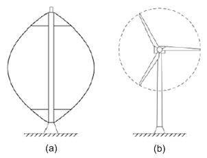
The main advantage of Vertical Axis wind turbines is that the gearbox and transmission systems are placed at ground level. Another advantage is their ability to capture the wind without considering wind direction. However, maintenance of these turbines is not straightforward as removing the rotor is often required. In addition, the captured energy is not efficient and large areas are compulsory for those turbines situated on land as guy-wire is necessary for supporting the structure.
Alternatively, the most recent wind turbines used are Horizontal Axis based with two or three blades. Having the rotor positioned on the top of the tower creates a more efficient system as more wind energy is produced. These turbines also have a nacelle, which held up by the tower and contains the gearbox and generator. A yaw system, which is turning the nacelle and rotor to face the wind, enables the turbine to capture the highest amount of energy. Additionally, some wind turbine blades have moveable blade tips, which are used as air brakes. Figure below demonstrates the components involved in a three bladed Horizontal Axis wind turbine [1].
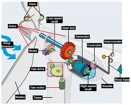
Here are brief descriptions of WT components [1, 2]:
- Rotor: The wind turbine blades and hub together.
- Blades: Extract kinetic energy from the wind and converts it into rotational mechanical shaft energy as a driving torque and wind turbine speed at a certain wind speed.
- Pitch System: Controls the angle of attack of the blades to the wind to control the extraction of kinetic energy and thereby the driving torque and speed.
- Brake: A disc brake to slow down and stop the rotor at cut-out wind speed or in over-speed emergencies.
- Low-speed shaft: Turned by the wind turbine rotor.
- Gearbox: Used to transfer rotational mechanical energy from the low speed shaft to the high speed shaft.
- High-speed shaft: Driven by the gearbox output coupled to the generator and drives the generator.
- Generator: Converts the rotational mechanical shaft energy from the high speed shaft into electrical energy, developing a reaction torque to the high speed shaft.
- Converter: Controls the flow of electrical energy from the generator by adjusting its rotational speed and therefore its reaction torque on the gearbox and wind turbine.
- Controller: Starts up and shuts down the wind turbine at the cut-in and cut-out wind speeds, controls the pitch, converter and yaw system to point the wind turbine into the wind and develop the appropriate reaction torque to the wind turbine at the given wind speed.
- Anemometer: Measures the wind speed and sends the data to the controller to assist in the development of the reaction torque.
- Wind Vane: Measures the wind direction and sends the data to the controller to control the yaw system.
- Nacelle: Housing on the top the tower to yaw into the wind and protect the drive-train assembly, shafts, gearbox, generator and converter.
- Yaw drive: Used to control the nacelle to face the wind as wind direction changes.
- Yaw motors: Power the yaw drive.
- Tower: Supports the nacelle at an appropriate height, as wind speed increases with height, taller towers enable WTs to capture more energy and generate more electricity.
There are a significant number of large, horizontal axis, WT manufacturers in the world, > 50 and their WT designs vary from manufacturer to manufacturer. However, the sub-assemblies described above are common to almost all manufacturers and this gives confidence in taking a common approach to all WTs.
Facts
A WF is a group of WTs in the same location used to produce electric power. A large WF may contain > 100 individual WTs and cover an extended area of tens of square km. In order to harvest wind energy more efficiently, the sizes of WTs have become physically larger and the WF location are usually built in remote plains, hills or sea regions. Currently, most WFs have been sited onshore, but there is growing interest in installing them offshore to take the advantage of the strong winds and lower environmental impact offered by offshore locations.
In UK, the government has set a target to produce 20% of electrical energy from renewable sources by 2020. According to [3], offshore wind power could contribute up to 19% of the UK renewable energy target by 2020. UK has a big potential for offshore WF locations to achieve a greater wind energy harvest because of its island geography. However, a major issue with sitting WTs at sea is the difficulty of access and potential high cost of O&M, which could contributes to high resultant cost of energy, making the energy produced from offshore wind less competitive compared to conventional sources. In comparison with onshore, offshore O&M is more difficult and costing more than onshore, and is estimated that they may represent 20-25% of the total potential income from an offshore WF [4, 5]. This is due to the following factors:
- Difficulty to access the site, the corresponding repair and maintenance techniques require reaching the WT by vessel or even helicopter;
- Delay in the first opportunity to carry out a visual inspection of suspected failure may be a several days or even weeks after it happened, due to weather conditions;
Extreme weather conditions may reduce the ability to perform the maintenance and repair.
References & Resources
- [1] F. D. Bianchi, H. D. Battista and R. J. Mantz (2007). Wind Turbine Control Systems: Principles, Modelling and Gain Scheduling Design. London: Springer, 2007.
- [2] D. Darling. The Encyclopaedia of Alternative Energy and Sustainable Living. [Online]. http://www.daviddarling.info/encyclopedia/W/AE_wind_turbine.html
- [3] 2009b, Digest of United Kingdom Energy Statistics, a national statistics publication. DECC, London.
- [4] M.R. Wilkinson, F. Spianto, M. Knowles and P. J. Tavner, (2006) “Towards the zero maintenance wind turbine,” in Proc. 41st International Universities Power Engineering Conference, vol. 1, pp.74-78, 2006.
- [5] B. Lu, Y. Li, X. Wu and Z. Yang, (2009) A review of recent advances in wind turbine condition monitoring and fault diagnosis, IEEE Conf. on Power Electronics and Machines in Wind Applications , pp. 1-7, 24-26 June, 2009.
Latest Post
- Dependency injection
- Directives and Pipes
- Data binding
- HTTP Get vs. Post
- Node.js is everywhere
- MongoDB root user
- Combine JavaScript and CSS
- Inline Small JavaScript and CSS
- Minify JavaScript and CSS
- Defer Parsing of JavaScript
- Prefer Async Script Loading
- Components, Bootstrap and DOM
- What is HEAD in git?
- Show the changes in Git.
- What is AngularJS 2?
- Confidence Interval for a Population Mean
- Accuracy vs. Precision
- Sampling Distribution
- Working with the Normal Distribution
- Standardized score - Z score
- Percentile
- Evaluating the Normal Distribution
- What is Nodejs? Advantages and disadvantage?
- How do I debug Nodejs applications?
- Sync directory search using fs.readdirSync